Hrvoje Lukatela
Geodyssey Limited
Calgary, Alberta, Canada
TileShare is a system for those that need to use and may want to share scanned large-scale paper maps for use on personal or mobile computers.
The TileShare system design assumes that a map is scanned once, and used many times, on computers of differing architectures, by many different users, in different applications. The format of the file in which a scanned map is stored is 'open', so that any programmer can create applications that facilitate the scanning of paper maps as well as the applications that view such maps, facilitate navigation by them or capture location data from them. Each scanned and "compiled" map file (a file with the extension ".tgxm") contains all of the information required to use it, so that it can be easily exchanged between users of TileShare based systems (via computer media, over the 'net, etc.). The internal format of tgxm files is very efficient, much more so than raw scanned bitmaps. Even when they cover large areas (and thus produce large disk files), such files can be used on hand-held systems having very little memory. This is achieved by "tiling" the scanned bitmaps and compressing their pixel data on a tile by tile basis. Thus such files are referred to as "tilesets".
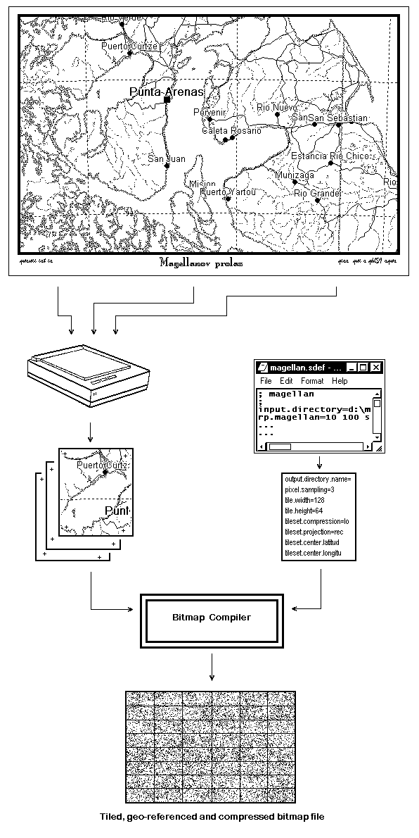
The creation of tilesets consists of three steps: scanning the paper map sheet - usually in more than one "section", then specifying the position of the scanned sections on the face of the Earth and finally specifying the characteristics of the desired tileset. Such definitions are contained in a simple text file, described in detail below. Finally, both the scanned bitmap files that contribute to a single tileset and the specification text file are processed in a "bitmap compilation" step to produce a single tileset (.tgxm) file.
The following is preliminary, in point form for the benefit of beta testers. Later, more advanced tileset compilers might dispose of some of the limitations stated below. In particular, a more sophisticated compiler will not require the scans to be "North up" and would be more flexible in the number and placement of the registration points.
The system is assumed to be used for maps of relatively large scale; typically between 1:25K and 1:250K, and not for high latitude locations. (Stereographic projection tilesets, better suited for polar regions, will be implemented later.)
Tilesets are assumed to be in the WGS 1984 datum. If the source map sheet is not in the this datum, adjustments must be made in specifying the coordinates of the registration points. In such cases, the latitude/longitude grid (if any) as depicted on the scanned bitmap may not coincide with the grid drawn over the bitmaps by the viewer program.
It is also assumed that a single tileset might be obtained by scanning more than one map sheet, but that its extent on the ground is not to exceed a few hundred kilometers in latitude, and significantly less than a hemisphere in longitude. (An extent specification of more than 20 degrees in latitude or 120 degrees in longitude is treated as an error.)
Scanned material must be "North up". There must be exactly four "registration points" per scanned section/file; placed in the general vicinity of the four corners of the scanned section. The ground area covered by each scanned section is assumed to be considerably larger than the ground area of a tile.
File names must be ASCII and must not contain blanks. Assume that the case of the letters is not material, i.e., that (some of) the systems on which a tileset will be used will not be able to distinguish between "SantaAna" and "santaana". The first letter of any name must be alphabetic (26 letter latin alphabet), followed by up to 31 letters, numerals or "_" (underscore). The material processed and produced by this system may be used on multiple computing platforms, therefore the best approach is to restrict tileset file names to lowercase letters only.
Input scans must be in the .bmp format, either rgb (24-bit) color or 256 palette based colors.
Specification file lines must not end with a backslash ("\").
Scanned sections must be (for now) .bmp files with 24-bit or 8-bit color depth. Best results are obtained if the scanning is done at such resolution that there is a one-to-one correspondence between input section and final tile-set pixels. This will, of course never be the case, if even the smallest geometry re-adjustment is necessary, as is, for all practical purposes, almost always the case. Still, if the correspondence is close, only "single-pixel discontinuities" will occur and these will be quite distant from each other and hopefully barely noticeable in the final tileset. Since tile width must be a multiple of 8, it will be required to find a particular combination of tile width, number of tile columns and longitude range of the tileset to achieve this. Since the tile height is given, but number of rows and unused space at the top and bottom required to accommodate the latitude range is calculated by the tileset compiler, no such consideration needs to be given to the tile height and number of tile rows.
Graphically, the process can be depicted as follows:
The scale of the output tileset should be such that the bitmap, observed on the computer screen, is of the same or slightly larger scale than the scale of the source paper map; note however that we assume that the tileset will be used on a variety of screens with somewhat different resolutions. Therefore the scale determination is an exercise in compromise and reasonable anticipation of the conditions in which the tileset will be used.
It is first worth noting that there are two values which must be given explicitly in the specification file: the width of the output tile (measured in pixels) and the longitude range of the final tileset. Thus the scale of the output tileset is determined by a third value: the number of tile columns. This value may either be given explicitly, or it might be left to the tileset compiler program to calculate it. (See also above, under "Scanning a Map Sheet").
If the number of columns is not given, two other values must be given: the scale of the original paper map and the resolution at which it was scanned. Using these values - and various internal assumptions - the program will compute and report the number of columns. If the scale of the resulting tileset is too small (e.g., the map on the screen is hard to use because the detail is too tiny) then the number of tile columns can be increased and the compilation run repeated. Conversely, if the map on the screen is more detailed than required, the number of tile columns could be reduced, and the compilation re-run.
The scanned material can also be distributed in "raw scan" form, together with the specification file. The end user can then adjust the scale (by experimenting with the number of columns setting) to generate a tileset that is best suited to his or her screen resolution and viewing preferences.
The tileset specification file is an ascii text file with a suggested extension of .sdef. It consists of a number of directives in the form:
keyword=dataand any number of comment lines, starting with ";" in column 1. Both input- and output-describing directives are placed in a single file. Their order is immaterial.
| Keyword | Data |
| input.directory | Directory of source bitmaps. |
| registration.tolerance | Maximum inconsistency in the pixel coordinates of registration points, assuming the same scale in x and y directions of the input bitmap and no rotational shift between North and bitmap x or y directions. If greater values are encountered it will be that either the pixel coordinates or the corresponding ground coordinates are in error. (Default is 16). |
| registration.y.invert | Integer, non-0 to invert direction of y pixel coordinate in the registration point directives. (cf. rp....). |
| rp.name | Registration point, four per scanned section - placed close to four corners of the section bitmap. The keyword part following "rp." is the complete name of the section file name. The data consists of four numbers: the first two are integers, x (measured from 0 at the western edge of the scanned bitmap eastward) and y (measured from the southern edge northward, (but cf. registration.y.invert) registration pixel coordinates), the third and fourth are the corresponding latitude and longitude of the registration point in ":" delimited degrees, minutes and seconds. Lower order sexagesimal units may be omitted, and the lowest one given can have decimal fraction. |
| add.name | Latitude and longitude additions. Two signed angles, being the values to add to all latitudes and longitudes of the four registration points in a scanned section. These values are commonly used to adjust for a paper map datum different from WGS 1984. Default values are 0.0, 0.0. |
| Keyword | Data |
| output.directory.name | Directory and file name of the output tileset (excluding the .tgxm extension). |
| pixel.sampling | Integer, the number of input pixels (in x and y directions) to be sampled to determine the color of one output pixel. An odd number between 1 and 9, inclusive. (Default: 1). |
| pixel.reduction.factor | Real number, the count of input pixels (in x and y directions) that correspond - in size - to one pixel in output tileset. (Less than 1.0 in the unlikely instance where one input pixel corresponds to more than one output pixel). This value need to be given only if the number of tile columns is to be be calculated by the program, and if different from 1.0 (Default: 1.0). |
| tile.width | Integer, the output tile width (pixels), an integer between 64 and 512, an exact multiple of 8. (Default: 160). |
| tile.height | Integer, the output tile height (pixels), integer between 32 and 256, an exact multiple of 8. (Default: 80). |
| tileset.color.depth | Integer, the output color depth: 1, 8 or 24. (1, 8 options to be implemented). |
| tileset.image.type | Method used to compress the output bitmap. Keyword values are lossless (default, similar to .png image files), lossy (similar to .jpg image files) or combined. ("lossy" and "combined" to be implemented). |
| tileset.projection | Name of the output projection. rectangular or stereographic. (Default is rectangular, stereographic to be implemented). |
| tileset.limit.north | Angular string, latitude of the northern limit of the tileset. |
| tileset.limit.south | Angular string, latitude of the southern limit of the tileset. |
| tileset.limit.west | Angular string, latitude of the western limit of tileset. |
| tileset.limit.east | Angular string, latitude of the eastern limit of tileset. |
| tileset.center.latitude | Instead of specifying the tileset limits, the extent on the ground can be specified as 'center' and 'range'. (This might be preferable for longitudes of tilesets that cross the 180th meridian). Angular string, latitude of the output set center. Ignored if south and north limits are given. |
| tileset.center.longitude | Angular string, longitude of the output set center. Ignored if west and east limits are given. |
| tileset.latitude.range | Angular string, output tileset latitude range. Ignored if south and north limits are given. |
| tileset.longitude.range | Angular string, output tileset longitude range. Ignored if west and east limits are given. |
| tileset.columns | Integer, number of tile columns in the output tileset. (Default: computed internally, assuming pixel.sampling is also the resolution reduction factor). |
| tileset.description.l1 | Free format characters, up to 30, line 1 of a description to be included in the output file. |
| tileset.description.l2 | As above, second line of a description to be included in the output file. |
tgxmview.exe is a "bare-bones" reference implementation of the program to view and use tilesets on a Windows computer optionally equipped with a GPS device transmitting NMEA sentences into one of its COM ports. The program needs no "installation" on the computer it is to be run on and requires no "configuration options" to be specified. It can be placed in the directory of the user's choice or it can be run from a CD (where it is, presumably, co-resident with a collection of tilesets). It can be initiated with the name of the selected tileset on its command line, or its [File] menu entry can be used to select and open the tileset to be viewed. Any number of instances of this program can execute simultaneously, displaying the same or different tileset files. The navigation around the tileset can be done either with the horizontal (East-West) and vertical (North-South) slide-bars, or by left-clicking on the desired map center-point. Right-clicking on a map point will display both its ground and tileset coordinates.
GPS tracing: In addition to the tgxmview program, the distribution contains a program called gpsmonitor.exe. This program enables GPS communication with the viewer(s). Only one instance of this program should be started at any one time. The program is configured at start-up time by an ASCII textfile named gpsmonitor.init, which, incidentally, must be co-resident with the gpsmonitor executable. The distribution copy of the .init file contains extensive comments regarding its content. There are, however, only two lines that most users would need to change: the specific COM port to which the GPS device is connected and the path and name of an optional log file. If the values in the CD distribution copy of the .init file (COM1 and no logging) need to be changed, both the gpsmonitor.exe and gpsmonitor.init must first be copied to a writeable hard drive; the .init file so that it can be modified, and the .exe file so that it remains co-resident with the .init file.
Once the gpsmonitor is up and running, a number (up to an implementation-defined maximum) of currently running instances of tgxmview.exe can request that gpsmonitor forwards its ongoing location information, in real time, as it is received from the GPS device. Once the option is activated within any of the viewers, a GPS trace can be displayed and its window can be set to move over its designated tileset so that the current position stays within its window.
If a fully qualified name of a log file is specified, gpsmonitor will open the file in "append" mode and will write to it a location/time record whenever such data is received from the GPS device (typically, every second). The format and content of the location/time record can be found in the gpsmonitor.c source code file.
Please note that all tilesets are assumed to be cast in the WGS84 datum. Thus, if the GPS device allows the selection of the datum, please ensure that this is the setting in effect. (If there are no datum options offered, then almost certainly this will be datum used by the device.)
bmpreg.exe is a simple Win32 GUI program that displays Windows .bmp files and allows the measurement of pixel coordinates. (The program has no menu of its own: file selection entry is incorporated into its "system" menu - activated by clicking on the icon at the left extreme of its title bar). Clicking with the left mouse button anywhere on the bitmap image displays the coordinates and at the same time loads the number strings into the Windows clipboard. If Notepad (or any similar text editor) is used to compose an .sdef file, the coordinates of registration points can be included in it without the need to re-type them.
widthcalc.exe is a command line program that will list possible combinations of tile widths and number of tile columns, sorted by the measure of their fit to the tile longitude range. It is invoked with six command line parameters, as follows:
px_s_w px_s_e long_s_w long_s_e long_t_w long_t_e
px_s_w and px_s_e are pixel X coordinates and long_s_w and long_s_e are longitudes (in the same format as the angular values in the .sdef file) of two points at the same or somewhat similar latitude on a single scanned section; probably of the two points used as the West and East section corner points along the North or South edge of a scanned section. These four values define the number of pixels per unit of longitude of the original scanned bitmap.
The two parameters that follow - long_t_w long_t_e - are the longitudes of the West and East limit of the tileset. With these known, the program will find the total number of columns required for each tile width between 80 and 512 pixels. (Tile widths must be multiples of 8). In the general case, the number of columns times the tile width will not equal the number of pixels that the tileset should ideally have, based on the pixel per unit of longitude value computed from the first four parameters and the longitude range defined by the last two parameters. The results will be sorted on the absolute value of the difference and printed on the standard output. From these, a tile width and number of columns can be selected such that the tile width is close to the desired value, but still having a reasonably close fit to the total pixel number.
gridder.exe is a command line program that can be used when the source paper map (to be scanned) contains no latitude/longitude grid. In such a case, an arbitrary grid (or tick-marks) may exist, or may be drawn on the map surface, so that each scanned section of the map has four near-corner points that can be readily identified on the raw scanned section file. The latitude and longitude of these points can be determined as follows:
First, four points near the corners of the entire map sheet must be identified and their coordinates determined - perhaps by visiting them in the field and taking a reading from a GPS device. (We will refer to these points by NE, NW, SE, SW - according to the map corner they occupy).
Next, all six distances between the four points are measured on the map. Then a text file is created containing the known coordinates and measured distances. Its format is as follows:
; comment describing the map or the project
 latitude-NW longitude-NW
 latitude-NE longitude-NE
 latitude-SE longitude-SE
 latitude-SW longitude-SW
;
 r-NW r-NE
 r-SW r-SE
 r-NW r-SW
 r-NW r-SE
 r-NE r-SW
 r-NE r-SE
latitude-NW, longitude-NW ... (etc.) are geographic coordinates of the four given points, in the order prescribed, and in the same format as the angular values in an .sdef file.
Lines such as 'r-NW r-NE' specify the distance between the given points NW and NE - presented such that the first value is the lower and the second the higher reading on a metric ruler joining the two points. (The order of points can of course be reversed, just so long as the first of the two values is numerically lower than the second). Both readings are real numbers, being meters and fractions thereof, most commonly consisting of four digits, assuming a tenth of a millimeter precision, the millimeters probably read directly and their tenths 'eye-balled'. (Note that the program will work no matter what units are used to measure the map, but since the ground distances are computed internally in meters, the scale value as reported by the program may have to be adjusted when compared to the published map scale).
The resulting file is submitted to the program by providing its name as the command-line parameter. The program will report (on the standard output) a composite scale - calculated as the mean of the ratio of six distances computed from the geographic coordinates and their equivalents measured on the map.
If the map is of relatively large scale, and if the field coordinates have been determined correctly, and if the distances on the map have been measured with adequate precision, the scale should be very close to the scale printed on the map, and the six values that follow should be commensurate with the precision with which distances have been measured on the map: they are the differences between the measured distances and the scaled-down computed ground distances.
Next, all distances from scan-section corner ticks - however many are required to divide the map sheet into sections that will fit on the scanner - and four control points are measured. The text file is appended with lines that look as follows (note the order of values):
ptID r-PT r-NW r-PT r-NE r-PT r-SE r-PT r-SE
ptID is simply a short string mnemonic which is included in the output line so that the point for which the coordinates are computed and printed can readily be identified in the output. What follows on the text line (one for each point for which the latitude and longitude is to be computed) are eight readings, giving four distances: from the point to each of the four control points. (The low/high reading pair format is similar to the control distance input mentioned above - note that four r-PT readings on one line will be different as the ruler is aligned along the point and each of the four given points in turn).
When this file is processed by the program it will repeat the output described above (mean scale and control distance differentials), to which it will append one line for each point, consisting of:
ptID latitude-PT longitude-PT d-NW d-NE d-SW d-SE sigma
ptID identifies the point and latitude-PT and longitude-PT are its geographic coordinates. Four values that follow are differences between measured and computed distances, scaled down to the map, in the same order as the distances given. Again, if everything was done correctly, the differences should be similar in magnitude and commensurate with the precision of the measurements. The last value is the computed 'sigma' (mean error) - it provides an indication of the precision (on the map) with which the coordinates have been determined. This would be expected to be in (sub)millimeter range; higher as the map scale becomes smaller and the precision of the control point coordinate determination and map distance measurement decreases.
The output from gridder.exe can be re-directed to a text file, from which the numeric coordinate strings can be "cut-and-pasted" into the editor used to compose the .sdef file.